

How To Draw A Rectangle In Autocad
Rectangle command
The rectangle command is used to create rectangles in our drawing.
There are two methods to depict a rectangle. In the first method, we can create rectangles randomly by specifying the points. In the second method, we tin can create rectangles by specifying the value (length and width).
Let's understand by 2 examples.
Example 1:
To describe rectangles randomly.
The steps are given below:
- Select the rectangle control from the ribbon console. The rectangle icon will await like the below epitome:

Or
Type Rec or Rectangle in the control line and press Enter. - Specify the first corner betoken on the viewport.
- Specify the second corner point (diagonally opposite to the first point) on the viewport.
Example 2:
To describe a rectangle past specifying the length and width.
The steps are given below:
- Select the rectangle command from the ribbon panel. The rectangle icon will look similar the below paradigm:

Or
Type Rec or Rectangle in the command line and press Enter. - Specify the first corner point on the viewport.
- Specify the length and latitude of the rectangle in the grade of @length, width. For instance, @iv,5.
Where, four is the length of the rectangle, while v is the width of the rectangle. - Press Enter.
Rectangle with round corners
The rectangles can also be created with rounded corners.
The steps to create a rounded corner rectangle are listed below:
- Select the rectangle control from the ribbon panel. The rectangle icon will look like the below prototype:

Or
Type Rec or Rectangle in the command line and press Enter. - Type F or Fillet and press Enter.
(Fillets are used to create round edges.) - Specify the fillet radius for the rectangle. For example, i.
- Printing Enter.
- Specify the outset corner point of rectangle on the viewport.
- Specify the length and breadth of the rectangle in the grade of @length, width. For case, @6,six
- Press Enter.
The rectangle formed is shown in the below paradigm:

Nosotros can besides blazon Superlative or E instead of Fillet to create rounded corners.
Rectangle with slanted corners
The rectangles can besides be created with slanted corners.
The steps to create a slanted corner rectangle are listed below:
- Select the rectangle control from the ribbon panel. The rectangle icon will look similar the below image:

Or
Type Rec or Rectangle in the command line and press Enter. - Blazon C or Chamfer and press Enter.
(Chamfers are used to create slanted edges.) - Specify the kickoff chamfer altitude for the rectangle. For example, 1.
- Printing Enter.
- Specify the second chamfer distance for the rectangle. For example, 1.
- Press Enter.
- Specify the first corner point of the rectangle on the viewport.
- Specify the length and breadth of the rectangle in the grade of @length, width. For instance, @7,6.
- Press Enter.
The rectangle formed is shown in the below paradigm:
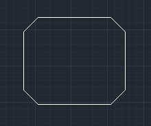
Note: The chamfer altitude for both sides should be the aforementioned to create regular shape.
Nosotros can also alter the shape co-ordinate to the requirements.
Rectangle with increased width
Nosotros tin can increase the width of the rectangle.
The steps to increase the width of the rectangle are listed beneath:
- Select the rectangle control from the ribbon panel. The rectangle icon will look like the below image:

Or
Type Rec or Rectangle in the command line and press Enter. - Type W or Width and press Enter.
- Specify the line width for the rectangle. For example, one.
- Press Enter.
- Specify the commencement corner point of the rectangle on the viewport.
- Specify the length and breadth of the rectangle in the form of @length, width. For example, @v,five
- Press Enter.
The rectangle formed (represented by blue lines for better visibility) is shown in the below image:
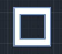
Note: We tin can perform multiple functions on a rectangle by specifying the value for each property.
To remove item property (ex. Width/chamfer), we need to specify the value 0 to the corresponding property of the rectangle.
Rectangle with increased thickness
We tin increase the thickness of the rectangle.
The steps to increase the thickness of the rectangle are listed below:
- Select the rectangle control from the ribbon panel. The rectangle icon volition expect like the below epitome:

Or
Type Rec or Rectangle in the command line and press Enter. - Type T or Thickness and press Enter.
- Specify the thickness of the rectangle. For case, 1.
- Printing Enter.
- Specify the kickoff corner point of the rectangle on the viewport.
- Specify the length and breadth of the rectangle in the class of @length, width. For instance, @6, v.
- Printing Enter.
The thickness will be in the Z direction and visible in 3D but.

Source: https://www.javatpoint.com/autocad-rectangle-command
Posted by: daviswallard1976.blogspot.com
0 Response to "How To Draw A Rectangle In Autocad"
Post a Comment